Heizungssteuerung für den Subraum
Jede Heizung bekommt eine von diesen Platinen. Die adaptiert einen Wachsmotor-Stellantrieb auf RS485. Die Steuerung läuft im Keller auf einem Linux, z.B. auf vogon.
- Im Prinzip kann die Platine auch zwei Heizungen, aber ich würde lieber die Kabel kurz halten und mehr Platinen verbauen. Am besten in Reichweite von dem Kabel, was am Aktor schon dran ist.
- Als Gehäuse eine Aufputz-Verbindungsdose.
- Als Protokoll über RS485 z.B. was in der Art von Modbus RTU, aber möglichst einfach halten. Adressvergabe per Taster auf der Platine und dann im Flash speichern, also z.B. Broadcast mit "Setze Adresse x, wenn gerade dein Taster gedrückt ist".
- RP2040 (Raspberry Pico) als MCU, weil der ist sinnvoller bezüglich Preis und Programmierbarkeit (siehe Notizen.md).
- Zusatzfeatures:
- WS2811-Repeater (d.h. ein WS2811 mit auf der Platine), da wahrscheinlich eine Ader im Kabel noch frei ist.
- 2x Heizung
- 4x Fensterkontakt (oder sonstiger Digital-Eingang)
- 2x 5V Digital-Ausgang für z.B. I2C, WS2812, DS18B20.
- Sofern wir keine anderen Temperatursensoren verbauen, sollten wir 1-3 DS18B20 pro Raum einplanen.
- 1x Analog-Eingang
- Verkabelung zum Rack durch ein dediziertes Netzwerkkabel (d.h. vom RJ45 trennen oder Adapter festkleben) oder ein neues Kabel legen (eher nicht). Eventuell gibt's schon eins für DMX, wo das noch mit rein kann.
- Anschluss im Gehäuse mit Federzugklemmen. Kabel kommen von oben rein und werden unten angeschlossen, damit genug Luft zum Einführen ist. Fast jede Ader hat eine dedizierte Klemme - nur die Power-Pärchen innerhalb eines Kabels brauchen eine Doppel-Aderendhülse. Keine Wago o.ä. zum Weiterverbinden nötig.
- Vorteil gegenüber Kabeln zu einer zentralen Steuerung:
- Weniger Kabel (aber nicht so viel weniger, dass das alleine zu kleineren Gesamtkosten führt)
- Einfacher anzubringen (finde ich) und wir brauchen nirgendwo eine Box für eine Zentrale.
- Bidirektionale Kommunikation, d.h. Kabelbruch ist einfacher zu debuggen.
- Strom wird gemessen, d.h. wir können das intelligent steuern.
- Zentrales Netzteil muss nur den Dauerstrom plus x abkönnen statt den Einschaltstrom pro Heizung.
- Eventuell können wir die Dauer-Leistung noch reduzieren durch PWM.
- Das könnte man natürlich auch mit zentraler Steuerung machen, aber nicht toll, wenn die ein Pi mit Relais-Board ist oder sonstiges aus ein paar wenigen, fertigen Teilen zusammengestecktes.
- Sinnvolle Auslegung bezüglich EMV (Einstrahlung und Abstrahlung) - zumindest ist das der Plan.
- Zusatzfunktionen ohne weitere Kabel zur Zentrale, z.B. Fensterkontakte. Auch für weitere Projekte, solange sie sich an ein paar Spielregeln halten.
- High-Level Teil kann in einem Linux passieren und das ohne ESP32 als Adapter auf LAN/WLAN, ohne Funk und ohne zusätzlichen Pi.
- Heizung im Keller kann mit dran, was man bei einer Steuerung pro Raum vermutlich eher weglässt.
- Nachteil:
- Kosten für die Platine sind pro Heizung statt einmal pro Raum.
- Zwar weniger Kabel, aber die müssen den Strom für alle Heizungen abkönnen.
- Initial mehr Aufwand (den aber zum großen Teil snowball übernimmt).
- Ich finde es so einfacher zu pflegen, aber man kann auch argumentieren, dass es komplizierter ist.
- Ersatzteil-Management: Wir werden direkt einige mehr bestellen wollen, weil wer weiß, welche Bauteile fehlen, wenn man
in ein paar Jahren Ersatz braucht. Wir brauchen 14, aber bezüglich Bauteil-Preisen dürfte 30 sinnvoll sein.
- Wir müssen mal schauen, ob es realistisch ist, einfach mal 5pcs zum Testen zu bestellen oder ob wir direkt all-in gehen.
- Bei gekauften Platinen hat man zwar im Prinzip das gleiche Problem und ob man was von Ali in 5 Jahren noch so bekommt ist doch sehr fraglich. Aber bei großer Box mit vielen Jumper-Wires fliegend verdrahtet wird man schon was anderes finden, was gut genug passt.
- Das ist aber immer noch besser als Custom-Platinen für zentrale Steuerung, weil bei vielen gleichen kann man welche auf Lager haben und einfach tauschen. Es ist halt wirklich nur diese Platine und der USB-RS485 und nicht noch weitere ESP32 oder Raspi oder so, die ebenfalls kaputtgehen könnten.
Errata for V1.0
No fix needed
- Varistor on 24V is more than fast enough but we could add a TVS in parallel for longer life span.
- Fix if we ever have a dead varistor (or one that has significant leakage current).
- WS2811 should have 33R series resistance.
- We do have 27R, which should be close enough.
- USB host mode might be useful.
- It was left out because we didn't have enough current available at 5V when that was decided. If we keep that in the next revision, we could consider it again.
- It might be useful for adding additional hardware but things like BLE and Zigbee are better added via SPI/I2C/UART, which should be easier (unless we have enough uses for low-speed USB to make a generic tunnel, e.g. as an USB-IP device on the other end).
- What would be needed?
- Pull CC lines high instead of low at the request of the MCU (needs another pin) but always pull them low by default (for the bootloader).
- Supply VBUS at the request of the MCU (needs a pin but maybe the same one).
- Current limit for VBUS, e.g. with PTC fuse.
- Alternative: External adapter to USB-A that also provides power supply (e.g. using our 5V output on J1 pin 14, which is already fused for 500 mA).
- Alternative: Attach device inside the case and use a different protocol (I2C/SPI/UART) or attach it to an existing Linux computer (if it doesn't have to run while the room is powered down).
Change for new revision (if we ever have one)
- WS2811 should have 100R series resistance on VDD.
- Datasheet sounds like this is optional for 5V so let's hope for the best.
- Hotfix is unlikely for current PCB so backup plan is to remove the WS2811.
- WS2812C-2020-V1 datasheet doesn't have the 33R series resistance but we maybe want to add it anyway.
- Add DCDC to main PCB if we have the space.
- We could use RT7272, which has an adjustable current limit. That way, we can use a smaller inductor but we will have less current available for external circuits (i.e. adjust the fuses, as well).
Hotfix would be useful
- RS485 common mode range goes from -7V to +12V but the TVS clamps it to -0.7V to 6V.
- If we use the full 12 A on 1 mm² wires (2x 0.5 mm²), we could have a ground offset of 4V. RS485 could handle that but not with the TVS clamping it to a smaller range.
- The TVS is shared by WS2811. WS2811 seems to have ESD diodes (educated guess based on abs max values) so the series resistors might even die before the diodes if it ever comes to that so the WS2811 should be fine (enough) without the TVS. Furthermore, the WS2811 is an optional feature while RS485 is essential.
- The RS485 transceiver has plenty of ESD protection already so it shouldn't need the TVS anyway. It was added as an afterthought because "it couldn't hurt" - oh, well, turns out that it can!
- (We don't actually know that this will be an issues, i.e. we haven't tested it, but we would rather be safe than sorry and it is easier to fix it from the start. Actually, we don't expect any issues at all with the main use case, which will only need at most 2 A instead of 12 A, but we don't want it to fail later after someone adds lots of LEDs.)
- Hotfix: Remove U11 (and maybe replace it by a suitable SOT-23 TVS just for WS2811)
- Proper fix for new revisions: Keep U11 for WS2811 but disconnect it from the RS485 signals. There are dedicated TVS for RS485 that we could consider.
- Side note: The WS2811 signal is from board to board so it should see a much lower ground offset. We would expect something like 0.5V, which is still in the spec. If we have an offset of 1V, we will send 19 mA through the ESD diodes (limited by the series resistor), which isn't great but should be harmless.
Planned changes before deploying the boards
(Those aren't really errata, of course, but we will do that at the same time as the hotfixes so this is a good place to put it.)
- Test, test, test!
- Adjust R64 to have suitable volume for the beeper (when inside the case).
- Add BZ1 and J1.
- Add DCDC board.
- Bend F3 upwards (and a bit to the left) to have more space for wires at J1.
- Add "Anschlussplan".
Next Steps
- order PCBs (JLC PCBA)
- order other parts (LCSC)
- test basic function (bootloader, flash, blinky, USB)
-
test essential functions
- LEDs
- RS485
- on/off control for heater
- some debug info on USB, e.g. debug console on emulated USB serial
- CJ431 (just measure the voltage)
- DCDC stand-alone test
- supply main board from 24V, shouldn't back-feed to VBUS
- measure VCC with ADC
- DIGIN1/2/3/4 (short to GND or not - like they will be with Reed switches)
- maybe DS18B20
- basic communication, i.e. write modbus code for RP2040 and Linux
-
test other functions (part of it can be in parallel with alpha/beta/gamma tests)
- measure heater current, with and without EN_MEASURE_CURRENT
- implement short-circuit detection for heaters
- WS2811: connect DIGOUT to WS2811-in and connect a few boards
- I2C: temperature sensor
- beeper: simple beeps; very optional: MIDI and PCM
- DIGOUT1/2: DS18B20
- ANALOG_IN1
- 5V ext, including to test the fuse
- display: buttons
- display, I2C: temperature sensor
- display, OLED
- display, touch
- display, WS2812
- MicroPython and/or LVGL for the UI
- measure heater current, with and without EN_MEASURE_CURRENT
-
alpha test:
- 1-2 boards (e.g. in .cook and .elab)
- actuator connected to board but not controlling the actual valve, yet
- preferrably with one display board for first user feedback
- What do we test here?
- Basic function.
- Unexpected issues.
- First user feedback.
-
beta test:
- mount boards in the final places, with final wiring
- including all display boards and all sensors
- If we want dedicated boards for temperature sensors (e.g. .make over the working area), we should also add them now.
- Connect as many actuators as we have (but don't buy any additional ones, yet). We can connect them to the valves if we want but the power use of the normally-open actuator would be a waste in summer and we might need them for additional tests (which is easier when they aren't already mounted).
- Log everything to InfluxDB+Grafana.
- What do we test here?
- Monitor for communication errors and other reliability issues.
- Logging and graphs.
- Optional: Dry-run for integrations, e.g. edi and/or home assistant.
-
gamma test:
- Normal operation for one room, e.g. .hack or .elab. If we do this in .hack, we might want to start without the third radiator because it is not so easy to reach it in case of problems.
- What do we test here?
- Basic temperature control.
- Unexpected issues.
-
rollout:
- buy and connect all the actuators
-
optional parts: hardware (optional, i.e. not necessarily done by us)
- Reed switches
- more DS18B20, e.g. two for each radiator
- control fans in .hack - can we simply do this with one of the heater outputs (with the high side connected to 12V, of course)?
-
basic software features
- RS485 USB adapter passed through to Python software in container on vogon.
- simple way of adding new devices, e.g. press ADR button on one device and set its
Modbus address via broadcast ("if your button is pressed, use this address from now on
and store that in persistent storage"). This can be CLI or web interface.
- In general, I would like to avoid using persistent configuration on the boards. The central controller needs to know some parts anyway (i.e. they might become inconsistent) and users can more easily change this on a Linux (including for boards that are currently offline).
- configuration, e.g. a YAML file with info for each device: Modbus ID, room, how many heaters are connected, with display board
- simple user interface with OLED and buttons:
- display actual temperature
- set desired temperature
- set duration
- automatically reset to standby temperature after some hours
- basic monitoring: preferrably Grafana, but CSV+syslog would do the job
- basic temperature control: simple two-point regulator will suffice
-
fancy software features, maybe for V1.0 (all semi-optional)
- simple web UI for configuration and troubleshooting
- semi-automatic adding of new devices, e.g. scan by UID and identify by button or LED
- auto-baud or switch-baud command, i.e. start at a safe speed by default but have a way to upgrade it (but without race conditions and other pitfalls, please!)
- auto-detect order of boards by WS2811 signal (if first board has DIGOUT connected to WS2811-in)
- auto-detect whether heater valve actuators are connected (via EN_MEASURE_CURRENT)
- auto-detect whether display is connected
- touch control in addition to buttons
- The buttons will always be available as a fallback unless the touch turns out to be exceptionally reliable.
- function of DIGOUT configurable by Modbus and maybe some auto-detection (scan for I2C and DS18B20 devices on start or when requested)
- diagnostics:
- detect when boards are reset (by changing some register from its reset value to "I have seen you" and boards respond to a certain broadcast after reset so we can easily find them during normal operation even if we have never seen them before)
- error counters for each device and maybe even full Modbus diagnostics, log to Grafana for each device
- send the correct error replies (Modbus spec seems quite reasonable for this, even if we won't see many of the errors in practice, e.g. register not supported); and log errors
- better user feedback
- use the beeper when it makes sense (and only then)
- notify when the timer is expired
- acknowledge user input in a responsive way (local feedback, quick!, intuitive) but also be honest (i.e. indicate when the central controller hasn't acknowledged a change, yet)
- power saving:
- dim or turn off display and LEDs when not in use (until button is pressed or touch detects hand is near)
- let the MCU sleep
- fancy heat control:
- measure resistance to estimate current position
- closed-loop control for target resistance instead of simple open/closed control
- optional: correct overshoot. The heat seems to need some time to distribute, i.e. resistance and position will continue change after power is turned off.
- Measure resistance to position curve.
- This could be good for a blog post.
- Measure resistance to heat of radiator curve (probably a long-term test, can be done later based on Grafana data if we have the sensors).
- Make a heating model for each room, e.g. measure step response for a few radiators and then see where this takes us.
- We will probably stop here and just use a PI/PID controller but we may want to compensate for dead time, e.g. estimate expected future change of heat based on valve position history (or radiator temperature if we have that) and add this to the currently measured temperature.
-
future software features in Python (all optional, i.e. not necessarily done by us)
- This can all be done in Python on Linux so we can defer this until someone needs it and then they can implement what they actually need and have a real-world use case to design the API for (which is usually a good thing unless you are very lazy and only design it for your case and your case alone).
- APIs could be HTTP or MQTT, for example.
- API: set desired temperature for each room (maybe with several settings for each room, each with a name, time range and priority)
- API: let devices on the network communicate with Modbus devices
- API: show info on display or LEDs
- fxk8y's UDP protocol for LEDs might be a sensible choice.
- API: add items to the menu and receive a callback when they are activated
-
future software features, (partially) in firmware
(all optional, i.e. not necessarily done by us)
- ringclock
- MIDI over Modbus
- PCM over Modbus (with Pulseaudio sink on vogon)
Main PCB
RP2040 microcontroller (like Raspberry Pico), power supply, terminal block and most of the functions.
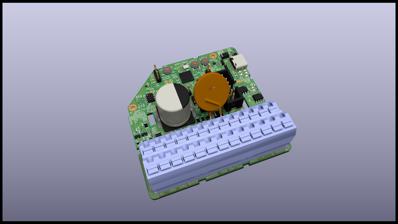
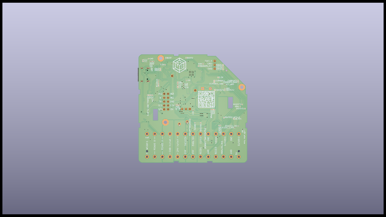
PDF with rendering of PCB layers
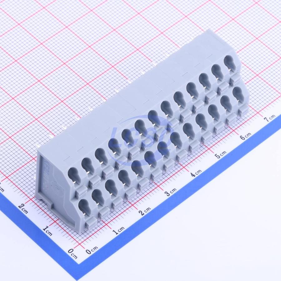
Anschlussklemmen: Es gibt leider kein Bild in richtig herum. Man kippe sie im Kopf um 90 Grad nach links-oben und die Kabel kommen dann von links-oben.
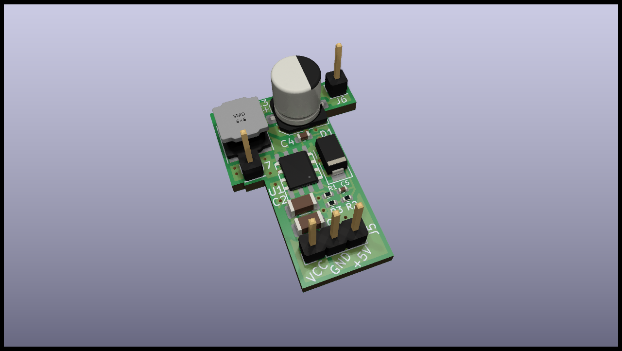
DCDC PCB
Da ich es zunächst mit LDO ausgelegt habe, aber der nicht genug Verlustleistung abkann, gibt es jetzt als Workaround dieses Aufsteckboard als Spannungswandler. Denkt euch die Stiftleisten weg. Dort sind Stiftleisten auf dem Haupt-Board und an denen wird es festgelötet (oder mit Buchsenleisten gesteckt). Die oberen beiden sind nur mechanisch:
PDF with rendering of PCB layers
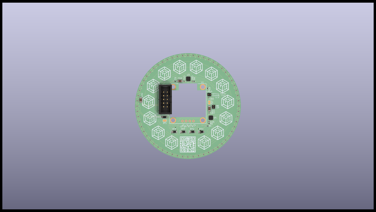
Display PCB
Some of the boards will also get a user interface, e.g. when there is a radiator in a good location for that. We should probably also have at least one dedicated control board for each room in a central location (i.e. most likely not near a radiator).
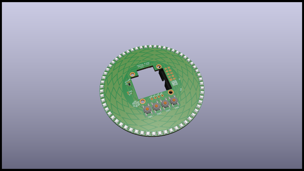
The hole in the middle will be filled by one of those small, cheap OLED boards:
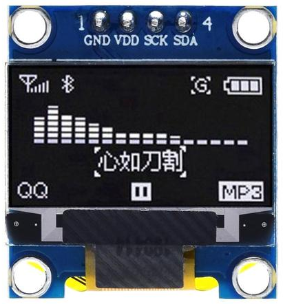
The OLED and four buttons are the "fallback" user interface. We can make this reasonably useful by providing shortcut actions, e.g. long press on left/right button to set room temperature to 17 resp. 21 °C.
There is a ring of touch areas and a ring of LEDs around the display. If they work as expected, they will be the main user interface: Double-tap a temperature of your choice to set it and the LEDs will be used to display set point and actual value. There will be some text and graphics on the case, e.g. an adhesive label with lines for the sector and temperature values printed on it.
The display PCB has an additional temperature sensor on the outside so it should provide a reasonable estimate of room temperature when it is placed in a central location between hand and eye level.
PDF with rendering of PCB layers
We plan to mill holes in the case for LEDs, fasteners, buttons and the display. The outlines are on layer User.4 and that is exported to DXF by KiBot. If touch is working, we should get the board as close to the case as possible (best would be below 0.3 mm but that's not realistic here). If not, we may want to add some spacers and reduce the hole for the display to only the active area. Best case would be that we have the best of both, i.e. touch is working and we can add some small spaces between display PCB and OLED board so we can make the hole small anyway. In either case, we may want to think about a thin layer of transparent PMMA. ahorn would like to have the buttons actuated via a piece of plastic, e.g. with suitable slots in the case instead of making a complete hole for the buttons. We will evaluate this further when we know how well touch is working.
Gehäuse
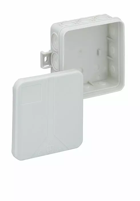
Die meisten Maße stehen im Datenblatt, aber für uns ist auch die Materialstärke vom Deckel relevant. Die scheint 1.5 mm zu sein bzw. 1.2 mm an den dünneren Stellen (gemessen mit der Mikrometerschraube von Paulimot). Das wäre deutlich dicker als die LEDs, d.h. man könnte versuchen, die nicht ganz durch zu fräsen.
tioan war nicht wirklich glücklich mit der Wahl, aber das war die einzig sinnvolle beim Hornbach (Preis, Größe und Form). Für zukünftige Projekte ggf noch mal mit ihm reden - er meinte, im Großhandel gibt's bessere zur Auswahl.
Kabel
fxk8y hatte Helukabel 18090 vorgeschlagen (aber nicht bei TME kaufen - ist woanders günstiger). 7-polig ist wohl recht üblich. Das sind 0.5 mm². Laut Faustregel kann es grob 5 A und laut Hersteller 6 A (aber ggf. sollten wir ein Derating anwenden je nach Art der Verlegung). Wir planen je zwei Adern für 24V und GND zu nehmen, d.h. 10-12 A. Die Klemme kann 12 A, das PCB hoffentlich auch.
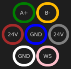
There doesn't seem to be any standard coloring for the wires of RS485 so we rather arbitrarily choose this because it somewhat matches our intuition. Furthermore, we should satisfy these conditions:
- RS485 A and B next to each other.
- Wires around RS485 have symmetric influence, e.g. 24V next to A and GND next to B would be bad because current flows in the opposite direction and will create an unbalanced voltage in the RS485 lines.
- WS2812 next to signals that balance each other out, e.g. both RS485 lines are fine but not only one of them.
Option 1: This is similar to our first, intuitive idea but with two power lines swapped to satisfy condition 2:
| A+ | B- | ||||
| 24V | GND | 24V | |||
| GND | WS | ||||
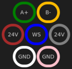
Option 2: WS2812 signal on center wire. This is not such a good match for intuition (blue is a signal and pink is GND) but all influences should cancel out and the central wire is not a power wire (i.e. doesn't get warm). This makes the most sense from a technical perspective.
| A+ | B- | ||||
| 24V | WS | 24V | |||
| GND | GND | ||||
Zusätzliche Nutzung
- Existierendes UI benutzen:
- Animationen auf den LEDs abspielen, wenn es grad keiner nutzt. Ebenso mit dem Display. Es muss natürlich in den normalen Modus schalten, sobald eine Taste gedrückt wird oder Touch-Event. Und evtl wollen wir schon die meiste Zeit die Temperatur anzeigen, aber die Ringclocks können ja auch Animationen und zeigen trotzdem meist die Zeit an. Das sollte sozial zu klären sein.
- Display und Touch können noch weitere Dinge mit steuern. Wie man das so umsetzt, dass es praktikabel ist, wäre zu klären (also z.B. keine ewig tiefen Menüs für Dinge, die mit dem SPS Display angenehmer gehen würden).
- Ich fände es sinnvoll, für so Dinge ein API über MQTT und UDP oder so bereitzustellen. Details müsste man sich noch überlegen.
- Platinen semi-dauerhaft "ausleihen":
- Wir werden 30pcs bestellen, aber nur 10-14pcs brauchen. Der Rest kann anderweitig genutzt werden, solange sie als Ersatzteile erhalten bleiben. Das gleiche gilt für die Display-Platinen, von denen wir 10pcs bestellen.
- TODO: Spezifizieren, welche Modifikationen ok sind, z.B. welche Lötjumper gesetzt werden dürfen, ohne dass man das später rückgängig machen muss.
- Firmware ersetzen ist ok, weil wir haben absichtlich MCUs, die ohne spezielle Hardware programmierbar sind.
- Auch die für die Heizung genutzten haben noch Kapazitäten für weitere Nutzung:
- Siehe oben für mehr Details zu den verfügbaren Pins und siehe Schaltplan für kreative Nutzung abseits des offensichtlichen, z.B. die Digitaleingänge als Ausgang nutzen.
- 3 IOs komplett ungenutzt (aber Beschaltung beachten), z.B. WS2812, DS18B20 oder I2C
- 0fr0 suggested two DS18B20 per radiator (one at each end) so we can double-check the function of actuator, valve and central heating.
- 4x Reed-Eingang, wenn nicht für Fenster genutzt.
- Der Wannenstecker kann im Prinzip genutzt werden, wenn kein Display dran hängt, aber nicht nach draußen legen, weil da ist keine Schutzbeschaltung dran. Wenn du das vorhast, nimm bitte ein dediziertes Board. Wenn ein Display dran ist, kann man nur noch was mit an den I2C hängen, aber dafür ist dann kein Stecker vorgesehen.
- Firmware muss bleiben, aber wir können Features in der allgemeinen Firmware ergänzen. Der Plan ist, dass man per Modbus-Register umstellen kann, welche Features aktiv sind.
- Im Zweifel bitte vorher nachfragen. Bitte nichts ins Gehäuse einbauen, ohne das abzusprechen!
- WS2812-Signal: Es war noch eine Leitung frei.
- An sich ist es für die Heizungen komplett ungenutzt und die fungieren nur als Repeater.
- Für wenige LEDs kann das erste Heizungsboard den WS2812 bespaßen. Wenn mehr Datenrate gebraucht wird, kann man einen ESP32 o.ä. pro Raum deployen. Da wäre ganz gut, wenn der ein API im Netzwerk bereitstellt, falls wir den WS2812-Ring für Auto-Discovery Dinge mitnutzen wollen. Und umgekehrt können wir discovern, wie viele LEDs zwischen den Boards hängen. An sich ist der WS2812 aber erstmal unabhängig vom RS485.
- Weitere Bus-Teilnehmer: Der RS485 Bus kann bis zu 32 Teilnehmer (weil darüber die Transceiver teuer werden). Solange du dich an
in paar Spielregeln hältst, kannst du dich mit dran hängen.
- TODO: Spielregeln definieren, z.B. sinnvoller Transceiver, Doku zu Adresse und wo (z.B. Wiki), Sicherung wenn mit an den 24V dran, Protokoll (sehr kleines Modbus Subset ist ausreichend; nur reden wenn gefragt), keine Stichleitungen, was sonst noch beachten beim Anschließen (z.B. 24V ausmachen und wie klemmt man sich an, z.B. Wago)
- RS485 kann man mit jedem UART sprechen. Manche können den zusätzlichen Enable-Pin selbst steuern, aber wenn der MCU halbwegs schnelle Interrupts hat, geht das normalerweise auch über einen GPIO (z.B. vollkommen problemlos auch mit ATmega).
- Die zentrale Steuerung wird voraussichtlich in Python geschrieben sein und auf vogon laufen, d.h. kann ergänzt werden. Sie sollte aber auch ein API bereitstellen, damit man einfach von anderer Software aus mit Geräten am RS485 Bus reden kann.
- Weitere Busse: Ein Netzwerkkabel hat 4 Pärchen und wir brauchen erstmal eins. Da kann nebenbei noch DMX oder differentielles WS2812 mit drauf. Oder ein weiterer RS485, wenn es Bedarf gibt (z.B. mehr Baudrate und dafür weniger zuverlässig oder weil wir die 31+1 Teilnehmer aufgebraucht haben). Einzige Bedingung wären, die anderen Signale nicht stören (d.h. differentielles Signal nutzen) und im Wiki dokumentieren (und falls es auch an vogon dran soll und in den gleichen Container, dann da an die Spielregeln halten).
Sonstiges
- PCBA:
- https://support.jlcpcb.com/article/84-how-to-generate-the-bom-and-centroid-file-from-kicad
- change header line in CPL to: Designator,Val,Package,Mid X,Mid Y,Rotation,Layer
- There is more to do, e.g. rotate components to match JLC's expectations.
- Use KiBot to make it reproducible:
nix develop -c time kibot - You can use the script
generate-pcb-outputs.shto run KiBot for all PCBs.