CyanLight PCB Documentation
This README will give you a short introduction to the PCBs of this project
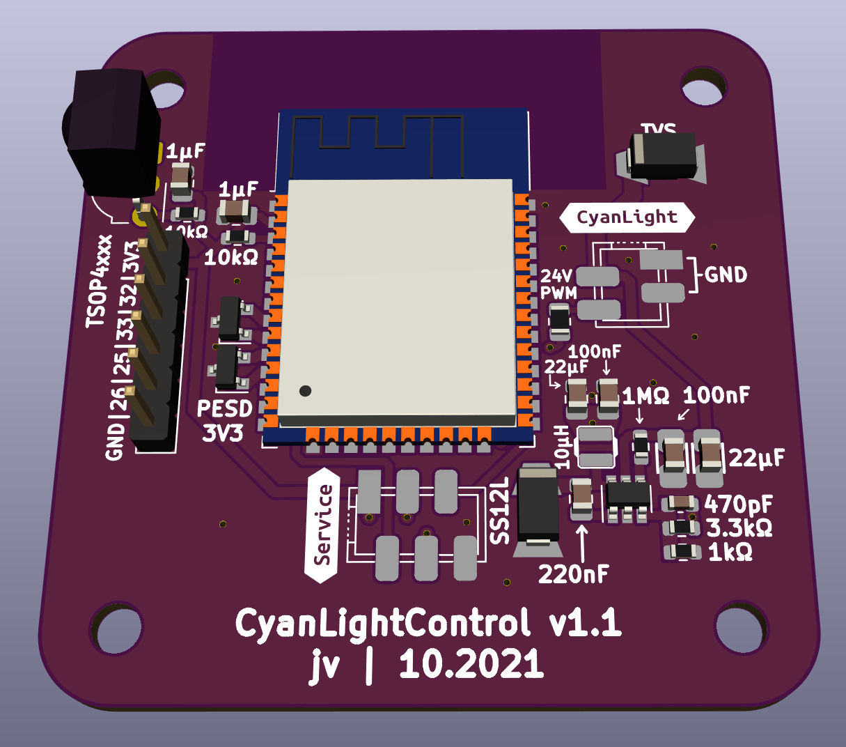
CyanLightControl v1.1
ESP32 powered companion board for CyanLight.
Contains 3.3 V buck regulator for effiecency and an experimental IR receiver.
Mates directly with the LED boards for power and PWM signal connection via Micropart-4 connector.
There never was a v1.0 of this board.
Pinout
| GPIO | Function |
|---|---|
| 27 |
PT4115 DIM |
| 23 | IR recv |
| 25 | general purpose |
| 26 | general purpose |
| 32 | general purpose |
| 33 | general purpose |
CyanLight LED PCBs
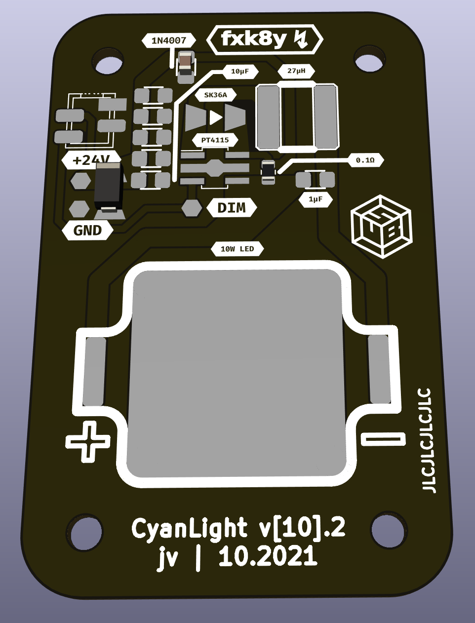
Simple PT4115-BreakoutBoard, initially designed for my special 490 nm LED but may also be used for generic projects
If you want to know more about CyanBus, CyanLight's new animation protocol suite on top of RS485 just goto the documentation of SiliconTorch !
Component selection
Current sensing resistor Rs
| I_LED | Rs | P | Min PKG |
|---|---|---|---|
| 0.1 A | 1.000 Ω | 10 mW | 0201 |
| 0.2 A | 0.500 Ω | 20 mW | 0201 |
| 0.3A | 0.333 Ω | 30 mW | 0201 |
| 0.4 A | 0.250 Ω | 40 mW | 0201 |
| 0.5 A | 0.200 Ω | 50 mW | 0201 |
| 0.6 A | 0.167 Ω | 60 mW | 0402 |
| 0.7 A | 0.143 Ω | 70 mW | 0603 |
| 0.8 A | 0.125 Ω | 80 mW | 0603 |
| 0.9 A | 0.111 Ω | 90 mW | 0603 |
| 1.0 A | 0.100 Ω | 100 mW | 0603 |
| 1.1 A | 0.091 Ω | 110 mW | 0805 |
| 1.2 A | 0.083 Ω | 120 mW | 0805 |
Inductor I
| I_LED | L |
|---|---|
| I > 1 A | 27 - 47 µH |
| 0.8 A < I ≤ 1 A | 33 - 82 µH |
| 0.4 A < I ≤ 0.8 A | 47 - 100 µH |
| I ≤ 0.4 A | 68 - 220 µH |
10W
Designed for the quadratic standard 10W LED modules. Running from at least 12V input voltage.
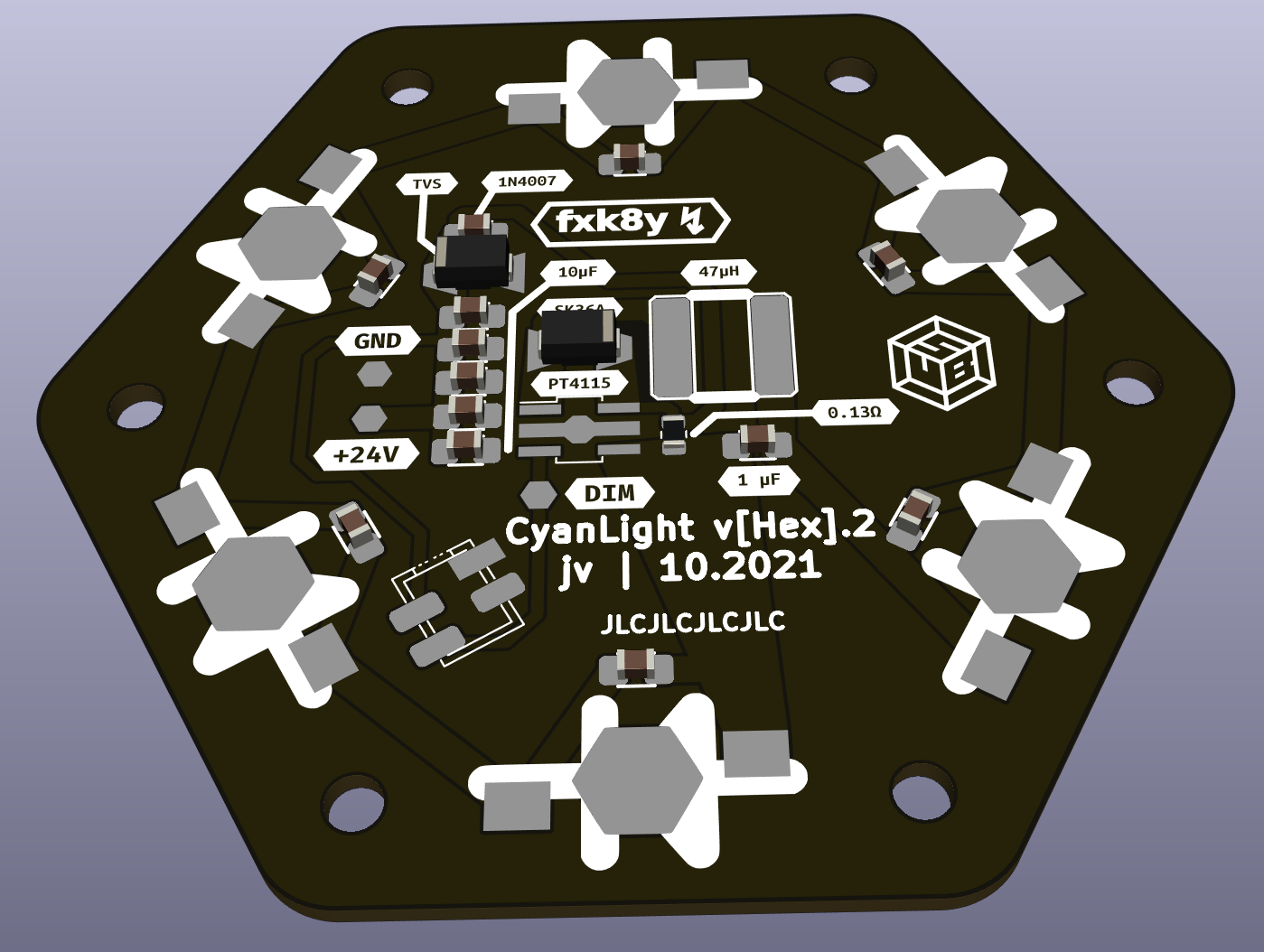
HexPCB
Designed for the standard 3W single-chip high power LEDs. Running from 12V - 24V depending of LED's forward voltage.
May be populated with up to 6 individual LEDs and contains 0805 footprints to bridge unpopulated LEDs with 0Ω resistors.


